Safety Information
Warning!
All wiring should be installed in accordance with local, state and national electrical code requirements under NEC/ANSI/NFPA 70. IMC threaded conduit, sealed fittings and proper electrical wiring practices should be adhered to. Improper installation can result in fire, serious bodily injury or death.
Warning! Pay attention to the following safety practices.
1) Never smoke or use an open flame anywhere near the tanks or dispensers.
2) All mechanical joints containing fuel products must be sealed with sealant tape appropriate for the product dispensed.
3) Never use any tools near the dispenser or tanks that can create unexpected sparks
4) Always have a fire extinguisher available in case of fire.
5) Always turn off all electrical power when working on any pumps or dispensers. There will always be a disconnect panel in reasonable proximity to the fuel island. Typically this will be a circuit breaker panel. Power must be turned off before working on any electrical circuits. Typical ratings are 20 to 30 amp circuits. If you are unsure of the location, always obtain assistance to locate the disconnect panel.
6) It is highly recommended that someone who is capable of rendering first aid be present during the installation process.
7) Follow OSHA lockout/tagout procedures during installation, service and maintenance.
8) Know where the emergency shutoff is located. Do not use emergency stops to disconnect electrical power. Always disconnect at the breakers.
9) Always cordon off all work areas from vehicle traffic.
10) The State of California cautions that fuel and fuel handling systems contain chemicals that are known to cause cancer or reproductive harm.
LINK Performance Specifications
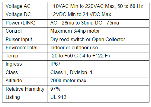
A. Installation – Standard Dispenser
A.1 Conduit Connections between Pump and LINK
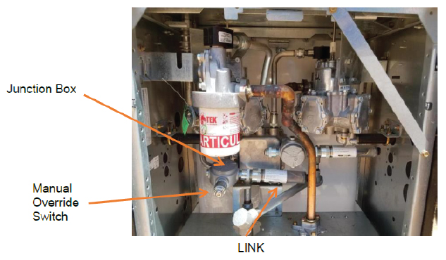
Installation for standard dispensers is quite simple. Most have an explosion proof junction box located in the bottom section of the dispenser. This junction box generally will have two or more conduits that feed into it. Normally there are additional available conduit openings in the junction box. Simply unscrew the cap from one of the unused ports and screw in the LINK. If there are no available openings you will have to use a rated Class 1, Division 1, T box (or purchase the optional hardware kit) to attach to the junction box and re-route an existing conduit to the box and then attach the LINK. The manual override switch can be removed from the wiring enclosure and inserted into an additional conduit opening in the junction box.
A.2 Wiring Connections
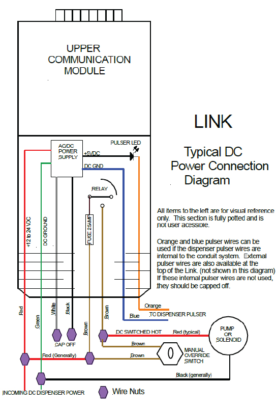
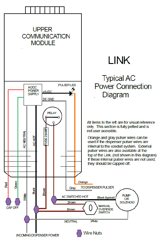
Once the LINK is installed, the control wires will be available inside the junction box the LINK is connected to. The wiring diagram on page 7 is also applicable here. You can control the dispenser solenoid valve, dispenser motor, dispenser control signal input or other such device. The installation typically involves disconnecting the AC power source, making the appropriate electrical connections and re-connecting the wires to the LINK and dispenser. Under no condition should a LINK control a pump motor larger than 3/4hp. Larger loads can be controlled with an external contactor or power relay. Your physical installation should be complete. Power the dispenser on, which in turn will power the LINK. You will notice a faint blue light in the top half of the LINK when power is applied. If there is no light, reconfirm that power is present. If no light is observed, recheck your electrical connections and try again. If no light is still not observed, call support for additional assistance.
B. Installation – Above Ground Tank
The LINK is designed to work with virtually any electrically operated dispenser, pump or solenoid. There are a large variety of dispensing systems and electrical connections and methods of connecting such devices together. It is not the intention of this manual to cover all possible combinations of connections. This manual will cover a “typical” installation however the installer should be sufficiently proficient in all aspects of dispensing systems to be able to understand how a LINK should be installed and to make sound judgments on how to modify a typical installation to suit the needs for any configuration that may and will be different from a typical one explained here.
B.1 Conduit Connections between Pump and LINK
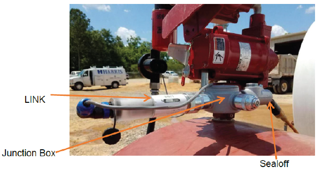
The kit contains the conduit fittings, bodies and connectors to install the LINK into a typical dispenser/pump. A typical installation for an above ground tank will look similar to the picture shown below.
B.2 Wiring Connections
The diagrams shown on the next page are the typical wiring connections for an AC / DC system. The diagrams show the LINK controlling either a pump motor or a solenoid valve. There are many ways of controlling dispensers including controlling a reset mechanism or providing an authorization signal to an electronic dispenser. The LINKS internal relay control is not connected to any internal power sources and the relay is mechanical and as such can control virtually any device. The power relay is protected by an internal fuse and cannot be replaced or changed. A test fuse can be provided if you are unsure of the power draw of the controlled dispenser. Use the test fuse in place of the LINK and run the full dispenser power through this test fuse before connecting the LINK. The LINK is fully warranted however if you fail to use the test LINK and blow the fuse in the LINK, it will not be replaced under warranty.
B.3 Pulser Connections: Utilizing Exiting Pulsers on Dispensers/Meters
Many dispensers and metering systems come already equipped with pulser units or can be equipped with third party pulsers. The LINK will interface with most of them. The LINK is equipped with 2 separate pulser inputs.
A) The first pulser input is a two wire combination that exits from the bottom of the LINK with all the other wires and is referred to as the LINK internal pulser wires. This input is used when the existing pulser wires are already internal in the conduit system.These two wires, orange and gray, are part of an optically isolated circuit. Connecting them together causes the optical circuit to flash. This in turn will pulse a single pulse each time the wires are connected. An external pulser will have to connect the two wires for each pulse. The gray wire is ground and the orange wire is positive.
B) The second alternate pulser input enters into the LINK at the top of the LINKthrough the 7 pin circular connector. The external pulser cable wires can beconnected to any pulser ouput by tying the wires together using wire nuts. The wiring from the LINK is designed intrinsically safe and can be safely run without conduit in a Class 1, Division 1 location or any lesser classification. Do NOT allow it to enter into a junction box, conduit or other device that could connect these pulser wires to external high voltage wiring.
B.4 Low Voltage Wiring Connections
Many dispensers and metering systems come already equipped with pulser units or can be equipped with third party pulsers. The LINK will interface with most of them. The LINK is equipped with 2 separate pulser inputs.
A) The first pulser input is a two wire combination that exits from the bottom of the LINK with all the other wires and is referred to as the LINK internal pulser wires. This input is used when the existing pulser wires are already internal in the conduit system.These two wires, orange and gray, are part of an optically isolated circuit. Connecting them together causes the optical circuit to flash. This in turn will pulse a single pulse each time the wires are connected. An external pulser will have to connect the two wires for each pulse. The gray wire is ground and the orange wire is positive.
B) The second alternate pulser input enters into the LINK at the top of the LINKthrough the 7 pin circular connector. The external pulser cable wires can beconnected to any pulser ouput by tying the wires together using wire nuts. The wiring from the LINK is designed intrinsically safe and can be safely run without conduit in a Class 1, Division 1 location or any lesser classification. Do NOT allow it to enter into a junction box, conduit or other device that could connect these pulser wires to external high voltage wiring.
Calibration of the Pulser vs the Meter:
Many pulsers must be calibrated unless you know 100% the ratio (example 10:1). The LINK along with the optional purchased pulser or if you are using an already installed pulser, you must read how many pulses are produced per unit of measure (gallons, liters, quarts, etc.). We will use the word gallon in this explanation, but it can be any unit of measure. To calibrate the pulser you must have an authorized cell phone/HUB. In the Information page, in the CLOUD, you will need to enter in the number of gallons pumped during calibration. The pulses field can be any initial number. You must contact your administrator to obtain authorization to run a calibration. Once authorized, you will have to either pump fuel into a calibrated container or use the existing meter on your dispenser to calibrate. If you have just installed the pulser (and you probably have at this point) you must pump at least 20 to 30 gallons back into the tank to purge the air out of the pulser and hose. For calibration, It is best to pump at least 10 gallons for high accuracy but a smaller amount can be utilized. To begin the calibration, refer to your cell phone user guide for the APP. Start a transaction and begin pumping into your calibrated container. If you are using your existing meter, then simply pump the fuel back into the tank or into a vehicle. Stop at a full gallon mark as close as you can. It does not matter how many gallons you pump but the more the better. (Please note that we refer to gallons, but the label is unimportant. You can use quarts, liters or anything else.) When you are finished, the cell phone/HUB will display a count. Call the administrator and report to them total gallons you pumped and the counts. That is all there is to it!
